Ready to Start you Retail Chain?
Become Top Products Retailer
Get Brand Tools, Machinery, Accessories and Equipment and Start your Retail Business

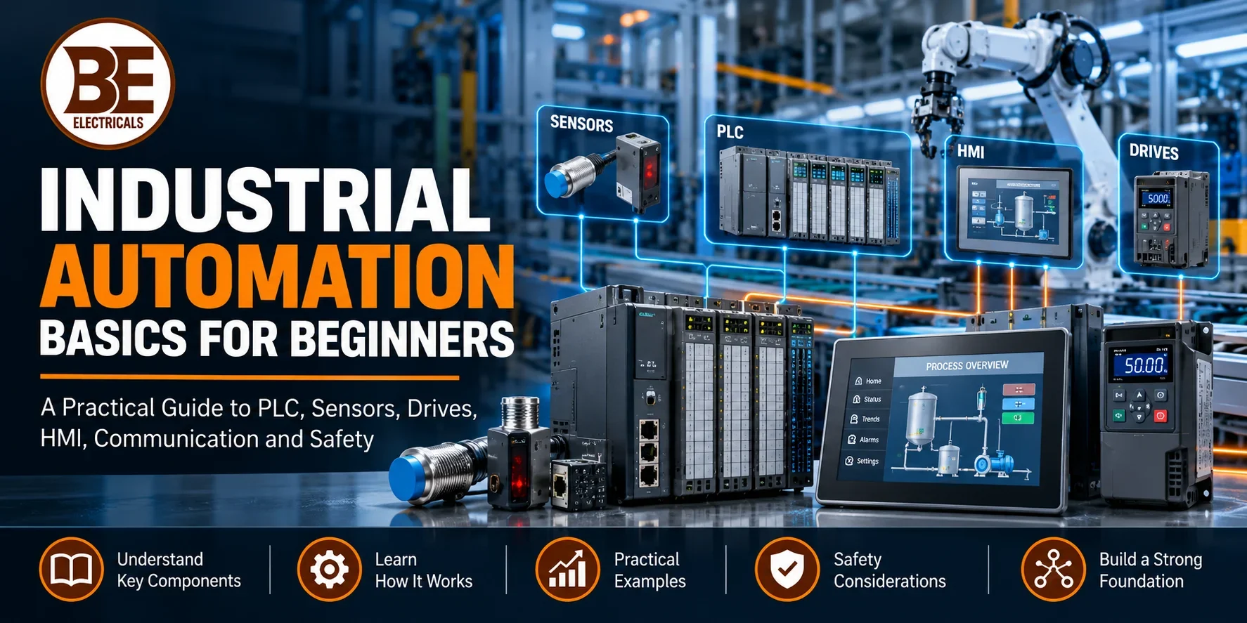
Industrial automation uses sensors, controllers, actuators, drives, operator interfaces and communication networks to monitor and control a machine or process. A basic loop is simple: a sensor detects a condition, the controller applies programmed logic, an output commands a device, and feedback confirms what happened. Real systems add protection, safety, alarms, data, maintenance access and defined behaviour when a component or communication link fails.
Start by learning the process before learning product catalogues. Draw what must happen, identify every signal, define safe states and only then select hardware. BE Electricals presents a broad industrial automation brand portfolio, including controller, sensor, switchgear, communication and motion categories. The portfolio is useful for sourcing, but a competent designer or integrator should approve the complete architecture and application-specific settings.
| Layer | Typical components | Core question |
|---|---|---|
| Field input | Sensors, switches, transmitters | What is happening? |
| Control | PLC, relay logic, controller | What should happen next? |
| Field output | Contactors, valves, drives, actuators | How is action produced? |
| Operator | HMI, buttons, indicators, alarms | What must people see or change? |
| Network/data | Industrial Ethernet, serial links, gateways | How do devices exchange information? |
| Safety | Guards, safety relays/PLC, protective devices | How is risk reduced independently? |
Write a plain-language sequence before creating logic. For a conveyor, the objective might be to start only when guards are closed, stop when an obstruction is detected, maintain a selected speed and alarm on motor overload. For a tank, it may be to hold level between limits while preventing dry running and overflow. This description becomes the basis for signals, equipment and tests.
Separate normal operation, manual mode, cleaning, maintenance, start-up, shutdown and fault recovery. Define who can issue commands and what happens after power returns. A clear functional description prevents the common beginner mistake of choosing a PLC, HMI or sensor before the required behaviour is understood.
Sensors convert a physical condition into a signal the control system can use. Common examples include inductive and photoelectric proximity sensors, limit switches, pressure and temperature transmitters, encoders and level devices. Selection depends on the target, range, response time, accuracy, environment, mounting, connector, output type and electrical interface.
BE Electricals lists product families such as Carlo Gavazzi industrial automation products and OMRON industrial automation products, with sensor categories on the live site. Use those pages to identify commercial options, then verify the exact sensing principle, supply voltage, PNP/NPN or analogue output, enclosure rating and cable arrangement for the application.
A programmable logic controller reads inputs, executes a program and updates outputs in a repeating scan. The program may include interlocks, timers, counters, sequences, calculations, communications and diagnostics. PLC hardware is designed for industrial environments, but the chosen family must still have suitable I/O capacity, memory, speed, modules, protocols and environmental ratings.
For a first project, prepare an I/O list and reserve sensible expansion capacity. Distinguish digital, analogue, high-speed and safety-related signals. BE Electricals shows Siemens industrial automation products, including PLC controller categories; confirm the model, module, firmware, engineering software and licence requirements rather than buying a CPU in isolation.
Imagine a pump controlled by tank level. A low-level switch requests filling, a high-level switch stops the pump and an overload contact reports a motor problem. The PLC checks mode, permissives and faults before energising the motor command. The HMI shows state and alarms, while a protective device interrupts power when an electrical fault occurs.
The sequence needs more than start and stop. Define contradictory sensor handling, maximum run time, restart after power loss, manual override, dry-run protection and alarm acknowledgement. Each requirement becomes a test case. This method helps beginners connect the process story to real I/O and avoids hiding safety-critical assumptions inside code.
A human-machine interface displays process values, equipment states, alarms and permitted controls. Good screens show the current situation clearly, use consistent symbols and keep abnormal conditions visible. The HMI should not become the only means of stopping hazardous motion or accessing a critical function that requires independent hardware.
Define users and permissions, units, alarm priorities, trends, language and data retention before building many screens. Avoid decorative animation that competes with useful information. Keep the PLC as the authority for interlocks, and treat the HMI as an interface that requests actions and presents verified status.
Contactors and motor starters switch and protect motors for suitable duties, while a variable frequency drive controls motor speed and torque within the approved application range. A VFD can improve process control and may reduce energy use in variable-torque applications, but it adds configuration, harmonic, cooling, cable and motor-compatibility considerations.
Select a drive using motor nameplate data, load type, speed range, overload duty, braking, supply, enclosure, ambient conditions and control method. Do not choose only by kilowatts. Confirm protection coordination, safe isolation and whether a separate safety function is required. Record final parameters during commissioning.
Relays isolate or switch control signals; contactors handle repeated switching of power circuits; breakers and fuses protect against defined electrical faults; disconnects provide isolation. Their functions overlap in a panel but are not interchangeable. Ratings must account for voltage, current, utilization category, short-circuit conditions, coil supply and the connected load.
Beginners should read the schematic as separate power and control paths. Follow the command from controller output to interposing relay or contactor coil, then trace the power path to the load. Confirm auxiliary contacts for feedback. A commanded output is not proof that a motor actually started.
Networks let PLCs, HMIs, drives, remote I/O, instruments and supervisory systems exchange data. Common systems use industrial Ethernet or serial protocols, but the name of a protocol does not guarantee plug-and-play compatibility. Devices must support the same implementation, data model, physical interface and configuration.
Create a network architecture with device addresses, switch locations, cable type, segmentation, time synchronization and ownership of configuration files. Separate control needs from office connectivity. Limit unnecessary access and plan secure remote support. When communication fails, each device should enter a defined, safe and diagnosable state.
Standard PLC logic can improve operation, but machine safety requires a formal risk assessment and suitable safety functions. Emergency stops, guards, light curtains, safety relays or safety PLCs, contactor monitoring and safe drive functions may be needed. The required performance depends on the hazard and applicable machinery requirements.
Do not bypass a guard in software for convenience or use an ordinary HMI button as the only emergency stop. Validate each safety function, record stopping behaviour and control access to changes. Product selection should follow the safety design, not lead it. Engage a competent safety professional whenever people can be exposed to hazardous energy or motion.
The I/O list is the bridge between process design, electrical drawings, PLC hardware and software. Give each signal a tag, description, type, range, normal state, fail state, terminal, cable and destination. Identify spare channels and special requirements such as isolation, intrinsic safety, high-speed counting or redundant measurement.
Review the list with process, electrical, mechanical, software and operations teams. Missing feedback signals are common: a valve may have an open command but no open proof, or a motor may have a run command but only an overload contact. The list should support both control and diagnosis.
| Selection item | Information to provide | Evidence to obtain |
|---|---|---|
| PLC | I/O, sequence, scan, memory, protocols | Configuration and module list |
| Sensor | Target, range, environment, output | Datasheet and wiring diagram |
| Drive | Motor, load, speed, duty, supply | Sizing sheet and parameters |
| HMI | Screens, tags, users, data and network | Screen list and licence scope |
| Panel | Loads, heat, fault level, environment | Drawings and thermal review |
| Safety | Hazards and required functions | Risk assessment and validation plan |
The panel must provide safe power distribution, protection, isolation, terminals, cooling, segregation, earthing and service access. Heat from power supplies, drives and contactors must be evaluated for the actual ambient temperature. Dust, moisture, vibration, corrosive atmosphere and washdown affect enclosure and component selection.
Prepare layout and wiring drawings before assembly. Keep power and sensitive signal wiring appropriately separated, label wires and terminals, and provide spare space without compromising heat flow. Panel construction and short-circuit protection require competent electrical design; a neat-looking enclosure is not proof of a safe or maintainable assembly.
Structure logic around operating states and clear permissives instead of scattered output coils. A machine may have stopped, ready, starting, running, stopping and fault states. Each transition should have an explicit condition and timeout. Interlocks prevent actions under prohibited conditions, while alarms tell the operator what failed and what consequence followed.
Use consistent tags, comments, reusable blocks and version control. Avoid hiding key values as unexplained constants. Simulate sequences and abnormal cases before site commissioning. Protect production programs with access control and retain a verified backup containing PLC, HMI, drive and network configurations.
Commissioning begins with drawings and inspection, not with pressing Start. Verify supply voltages, protective devices, earthing, terminal tightness where specified, device identity and network configuration. Perform point-to-point I/O checks so each field device changes the correct software tag and each output reaches the intended load.
Test normal sequences, interlocks, alarms, sensor failures, emergency stops, power loss, communication loss and restart behaviour. Record results and close deviations. Operator training should cover permitted modes, alarm response and when to escalate. The final handover should include drawings, code, parameters, backups, manuals and spares information.
When a machine stops, begin with safety and the process condition, then move through power, field device, wiring, I/O status, controller logic, network and output device. Check evidence at each layer instead of replacing several parts. The PLC diagnostic screen can show what the controller sees, but it does not automatically prove the physical sensor or load is healthy.
Use timestamps, alarm history and trends to reproduce intermittent faults. Compare current behaviour with the approved sequence. Record changes and restore temporary forces or overrides before returning equipment to service. A disciplined method reduces downtime and avoids creating a second fault during investigation.
Automation systems can be affected by unauthorized access, weak passwords, uncontrolled laptops, obsolete firmware and exposed remote connections. Apply least privilege, controlled accounts, secure backups, documented network boundaries and an approval process for changes. Coordinate security with operational needs so protection does not block safe maintenance.
Maintain an asset list with model, firmware, address, location and support status. Test backups and recovery procedures. Review vendor advisories through an approved process. Do not connect a new device or cloud service directly to a production network because it is convenient; assess the data flow and failure consequences first.
Define the process, write the sequence, identify hazards, build the I/O list, choose the architecture, prepare drawings, select model-specific hardware, program in modules, test offline, inspect the panel, commission point by point and train operators. Freeze baselines at each stage so mechanical, electrical and software teams work from the same revision.
BE Electricals explains its sourcing background and product scope on the About Us page. Use supplier guidance to compare commercial options, while keeping design, programming and validation responsibility explicit. Beginners learn faster when every product decision is tied to one documented function and one acceptance test.
Count current I/O, network nodes, program needs and likely approved additions. Then select a platform with enough headroom for diagnostics and realistic expansion. Excessive spare capacity raises cost and can encourage uncontrolled additions, while a fully occupied controller leaves no room for commissioning discoveries. Apply the same reasoning to panel space, power supplies and network ports.
Document which spare channels and addresses are reserved. Do not confuse physical slots with usable system capacity; firmware, licence, backplane power, scan time or protocol limits may govern first. Ask suppliers for a model-specific configuration rather than a family brochure alone.
An alarm should tell the operator what happened, where it happened, the consequence and the permitted first response. Avoid flooding the screen with repeated symptoms from one root cause. Prioritize hazards and production stops, apply appropriate delays, and distinguish an alarm from an event or maintenance reminder.
Review alarm history after commissioning. Frequent standing alarms train operators to ignore the system and hide genuine faults. Any change to limits or delays should be approved and recorded. Useful alarms connect process knowledge with control logic instead of merely repeating a raw sensor state.
List critical components whose failure would stop production and compare their lead time, interchangeability and configuration needs. Holding one PLC or drive in a cabinet is not enough if firmware, option cards, programs, passwords or connectors are missing. Verify storage conditions and periodically confirm that backups can be restored.
Track product lifecycle notices and approved replacement paths. Where multiple brands are used, document the reason and integration responsibility. A planned migration is safer than an emergency substitution during a breakdown, especially when safety, communication or motion functions depend on model-specific behaviour.
It is the use of sensing, control, actuation, communication and operator systems to monitor and control industrial machines or processes.
The PLC executes control logic; the HMI presents information and lets authorized users request actions or enter settings.
An input is a signal received from a sensor, switch, transmitter or another system.
An output is a controller command to a relay, contactor, valve, drive, indicator or other actuator.
They provide feedback about position, presence, pressure, temperature, level, speed and other conditions needed for decisions.
No. It is useful when variable speed or controlled acceleration is needed, but suitability depends on the motor, load and system.
Only when the complete safety design and selected equipment are suitable for the required safety function. Ordinary logic alone is not enough.
It is a structured register of every control signal, including its type, range, source, destination and behaviour.
It is an agreed method for devices to exchange data; compatible protocol names still require correct configuration and data mapping.
Use a justified allowance for expected changes in I/O, memory, network and panel space rather than one universal percentage.
Back up PLC and HMI projects, drive parameters, network configurations, licences where applicable and final drawings.
Send the application, I/O and motor data, environment, preferred brands, protocols, quantities, drawings and delivery requirements.
A reliable automation project starts with a clear process objective, verified inputs and outputs, suitable control hardware, safe failure behaviour and disciplined commissioning. Share the machine function, I/O list, motor data, preferred brands, network requirements, panel environment, quantity and delivery location through the BE Electricals contact page. Ask for model-specific product options and documentation, then let the system designer or integrator confirm compatibility, programming and safety responsibility before purchase.